Having explored our detailed case studies, that show the real-world impact of our solutions and get inspired on how we can help elevate your project to the next level.
Challenges and Objectives
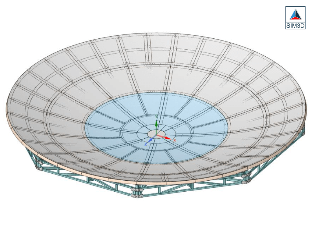
The client faced the challenge of ensuring the antenna\\\\\\\\\\\\\\\’s structural integrity under varying wind load conditions. The objective was to determine the pressure distribution on the antenna due to wind load using CFD analysis, and assess its structural performance by FEA analysis.


Methodology (Solutions Implemented)
1. Modeling: The antenna was modeled to create an accurate representation of its geometry and structural features.
2. Boundary Conditions:
a. Incident Wind Velocity and Wind Direction: The simulation considered the actual wind speed and direction expected at the antenna location.
b. Wind Load: The anticipated wind load on the antenna was applied as a boundary condition to simulate real-world conditions.
c. Structure Details: Detailed specifications of the antenna\\\\\\\\\\\\\\\’s material properties, dimensions, and mounting were incorporated into the model.
3. Loading Conditions:
a. Wind Load and Incident Direction of Wind: The wind load and direction were applied to the model to simulate the effect of wind on the antenna\\\\\\\\\\\\\\\’s structure.
4. CFD Analysis & FEA Analysis: CFD Analysis performed to obtain Pressure Values. The pressure values obtained from the CFD analysis were used to further refine the loading conditions, ensuring accuracy in the simulation.
Benefits (Results Achieved)
1. CFD Analysis for Pressure Distribution:
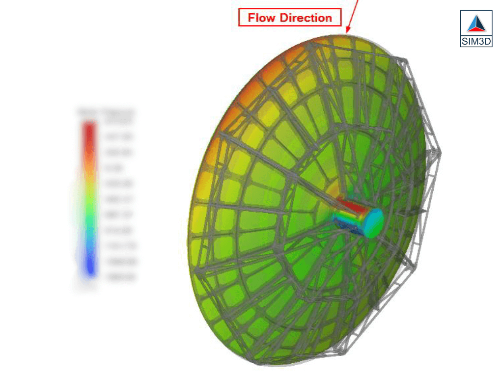
The CFD analysis was conducted to study the pressure distribution on the antenna\\\\\\\\\\\\\\\’s surface caused by wind loads. This analysis provided detailed insights into how the wind pressure varied across different parts of the antenna.
2. FEA Analysis for Structural Strength Verification:
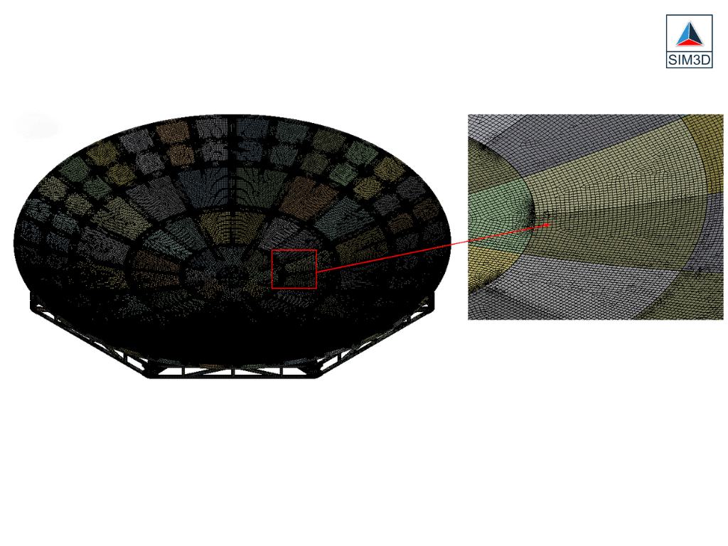
The pressure values obtained from the CFD analysis were used as input loads for the FEA analysis. FEA analysis was employed to simulate the structural response of the antenna under these wind-induced loads. This analysis helped verify the structural strength of the antenna and identify areas of potential stress or deformation.
3. Optimization of Antenna Design:
By understanding the pressure distribution and structural response, the client could optimize the antenna\\\\\\\\\\\\\\\’s design. Changes such as reinforcement of critical areas or modification of the overall structure could be made to enhance performance and durability.
4. Enhanced Performance and Durability:
The optimized design resulting from the analyses led to improved performance and durability of the antenna under wind load conditions. This ensured that the antenna could withstand expected wind pressures without experiencing significant structural issues.
5. Cost and Time Savings:
By using CFD and FEA analysis, the client avoided costly physical testing and prototyping. The virtual simulations allowed for quicker design iterations, leading to faster development times and cost savings

Summary of Project
By performing a steady-state CFD simulation & FEA analysis, the project successfully verified the structural strength of the antenna under various wind conditions. The analysis highlighted pressure distribution on the panels, providing valuable insights for structural optimization.

